I gained both theoretical and practical knowledge of rocket fundamentals, including assembly techniques. The theoretical aspects covered launch to recovery phases, aerodynamics, and the use of OpenRocket (CFD software), as detailed in the report on Rocket Level 1. I highly recommend reading the report to appreciate the depth of learning I gained. Practical skills included attaching the rocket using fiberglass and epoxy, and crafting the parachute and fins. Overall, the rocket performed successfully during flight and recovery.
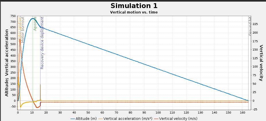
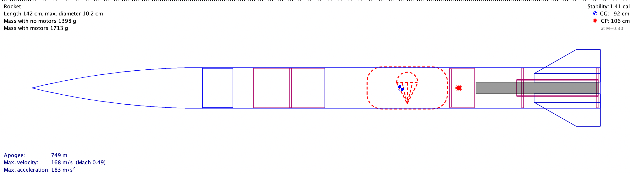
For Rocket Level 1, I worked in a team with five other people. A report is required for the design of the rocket and its justification. We chose to develop a rocket to reach maximum height without changing the propellant, emphasizing aerodynamics. This involved researching how a rocket works, from launch to recovery. Aerodynamics for the rocket were essential for achieving maximum height, as the rocket fuel cannot be changed, making CFD software and existing data essential for parts of the rocket's justification. The report with the rocket's design and simulations is shown below. This is the link if the level 1 Rocket Report doesn't show up
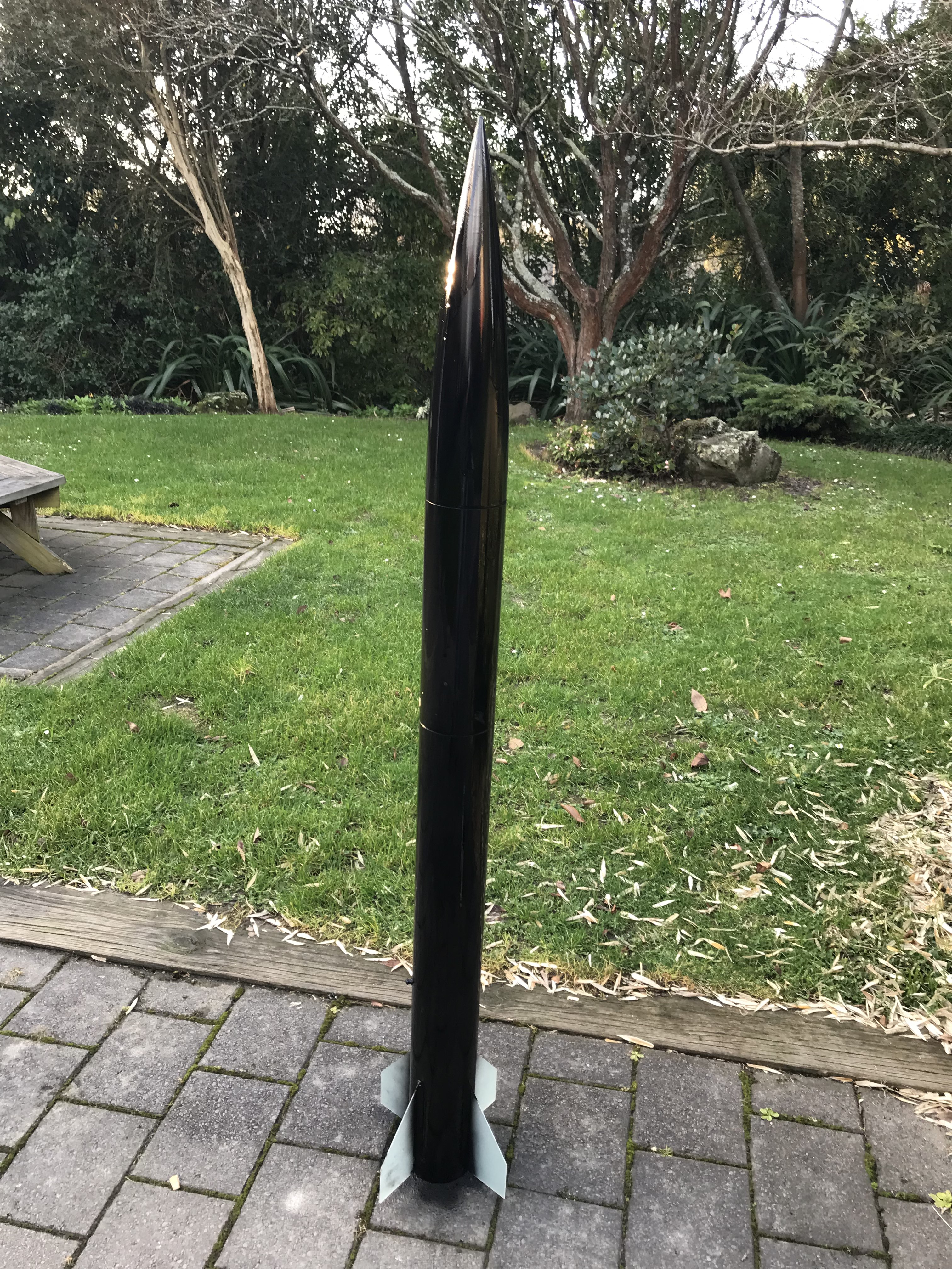
For Rocket Level 1, we used pre-made parts that required sanding and epoxy application before assembly. I learned the basics of workshop skills and how minor factors can affect launch or recovery success. For instance, uneven sanding of the fins can cause instability and prevent vertical ascent. I also learned about parachute construction, including its size and deployment considerations based on apogee or velocity. The finished rocket is shown below.
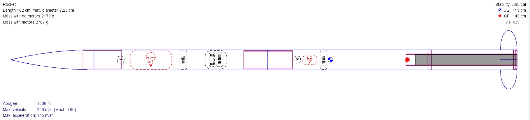
In Level 2 Rocketry, the project is undertaken individually. I am tasked with designing and manufacturing a rocket from scratch with the goal of achieving a mission altitude as close to 1200 meters as possible. My objective for Level 2 is to gain proficiency in manufacturing complex designs using fiberglass and other composite materials. I have already completed the report and will proceed to build the rocket.
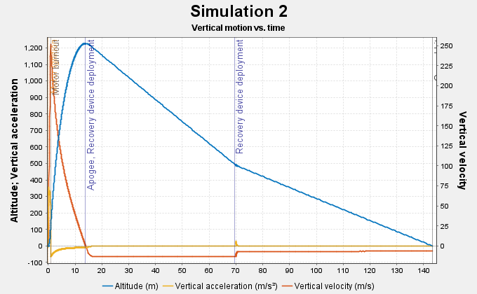
For Rocket Level 2, a report is required. I utilized previous knowledge to create the report (shown below), with the main difference being that I designed the rocket myself and used a J-class motor. The challenges I needed to address included ensuring the safe launch and recovery of the flight computer and ensuring its accessibility. Additionally, I must determine the optimal altitude to maximize recovery chances while achieving maximum height, decide on the parachute deployment timing, and identify the necessary materials for each part of the rocket.This is the link if the level 2 Rocket Report doesn't show up
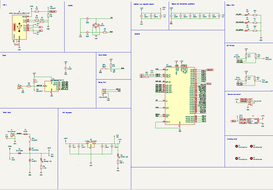
The PCB tutorial, conducted by UC Aerospace Club, introduced me to the basics of KiCad and electronics required for developing a flight computer. Following the tutorial, I integrated additional components into the PCB, including a buzzer and an Ra-02 LoRa module for long-distance communication, which were approved by the tutors. I learned from challenges, such as poor decisions in component placement made using the editor, but eventually corrected them. This system will be incorporated into my Level 2 Rocket to provide flight performance data.
This is the finished schematic (shown below) of the PCB, featuring the recommended components (buzzer and LoRa, detailed further below). The design aims for clarity to facilitate understanding and familiarity with KiCad software operations. The schematic will be sent to the manufacturer for production and subsequently soldered by me at the university.
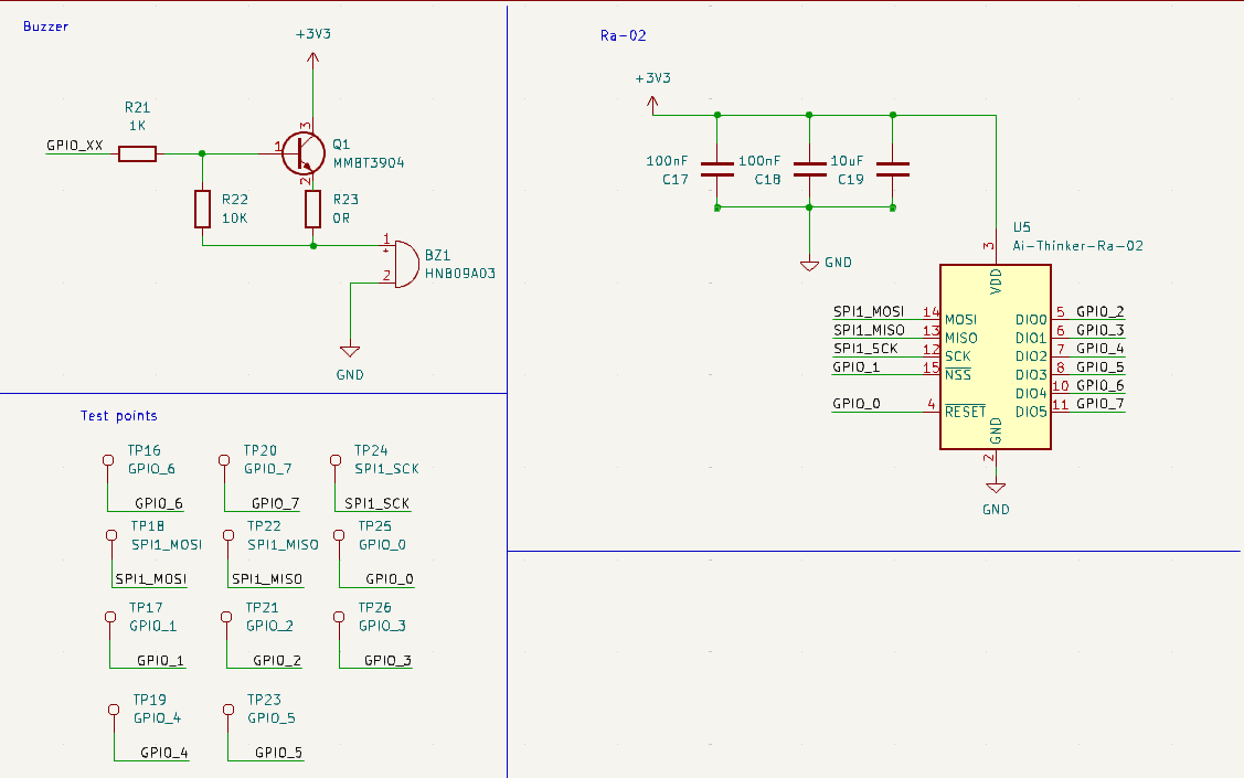
The 0-ohm resistor with the buzzer allows for easy adjustment: if the buzzer is too loud, a resistor can be substituted to reduce its volume. The transistor is included because it requires more current than the CPU. As for the LoRa module, I incorporated testing points to simplify troubleshooting in case of PCB issues
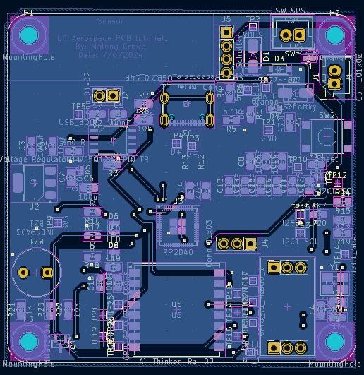
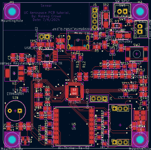
I encountered the most difficulties with the KiCad editor, having to redesign my PCB layout more than three times. Adjustments included resizing the board after realizing it didn't fit, and relocating the microcontroller to a different area (as shown below). The entire process took approximately 20 hours to complete.
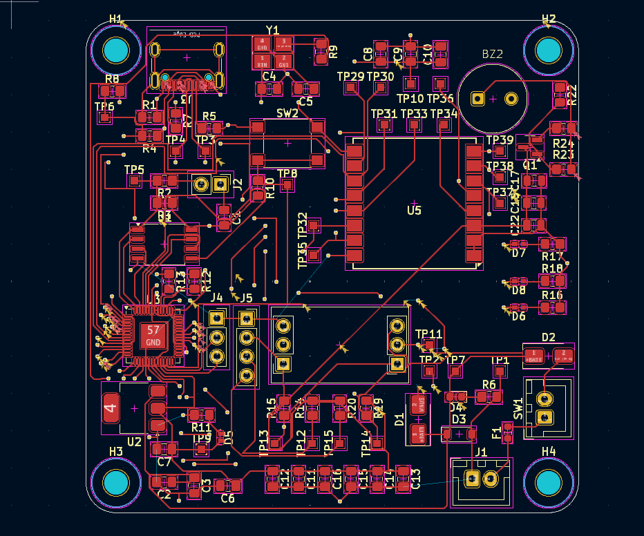
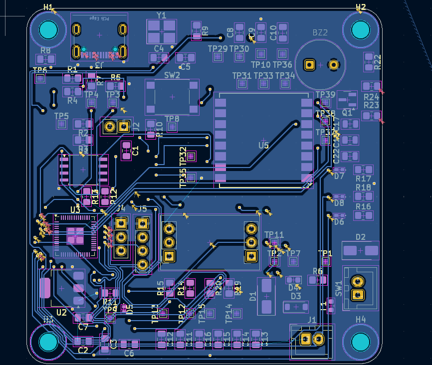
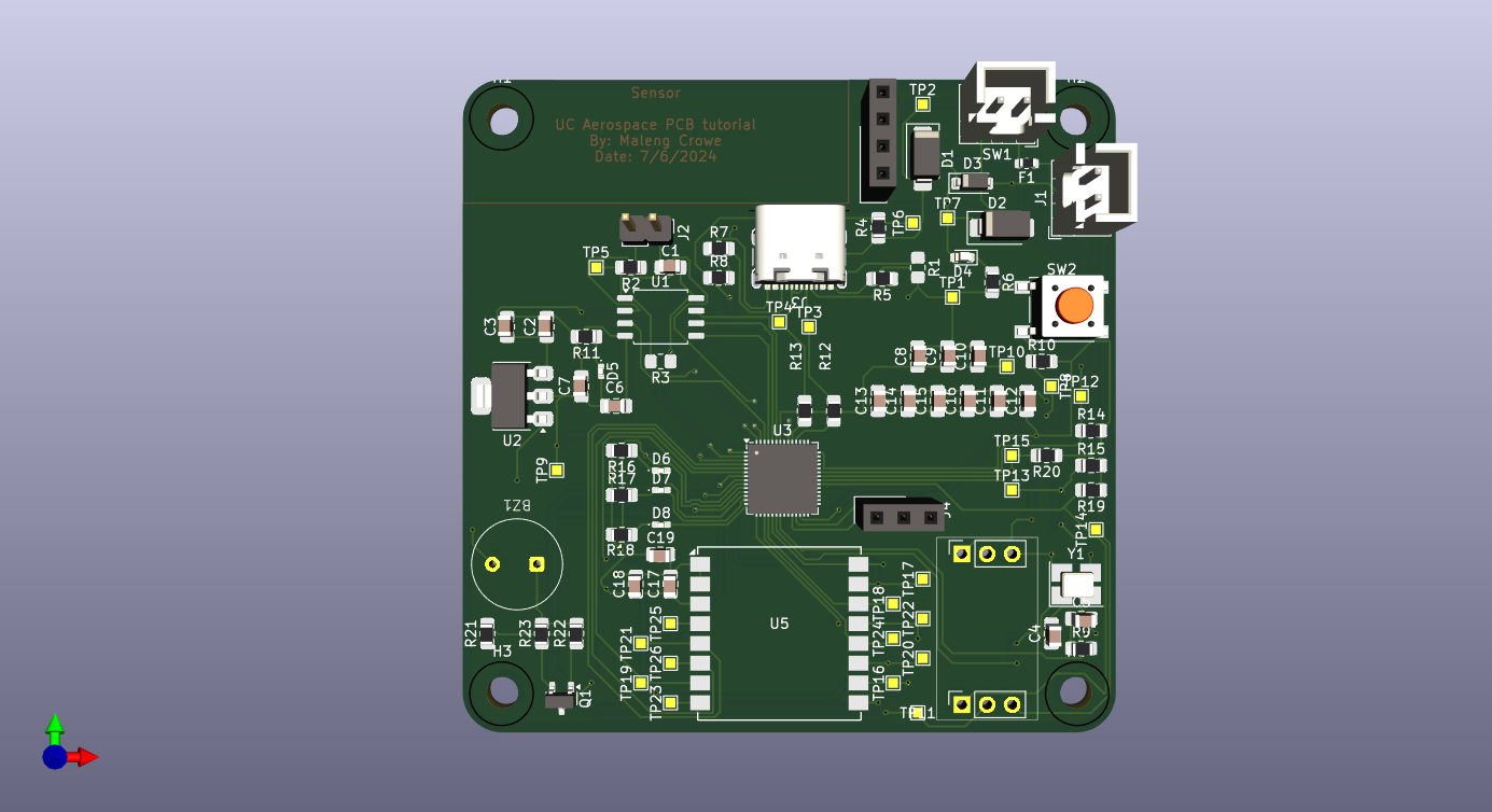
Below is the finished PCB as shown in the PCB editor and a 3D rendering of its appearance. Overall, I gained valuable knowledge from this tutorial and plan to apply these skills in future PCB projects. I am grateful to UC Aerospace for their guidance in helping me build my first PCB and for teaching me the fundamentals of electronics.
The Hot Rocket Launch System is designed to detonate rockets from a safe distance. Currently, I have conducted cost analysis and designed the appearance of the Hot Rocket System to determine the necessary dimensions for the casing.
I am assisting with the L1/L2 flight computer for the UC Aerospace Club, specifically focusing on the sensors. I will provide an update during the term break.